

Product brochure
Whitepaper
Sub-cell turning to accomplish micron-level alignment of precision assemblies
High-Precision Mounted Lens Production
Directional adhesive bonding versus alignment turning
Download
High Precision Lens Assembly with Alignment Turning Machines
On Machine Metrology for the Alignment Turning Process
Download
Application Report
Cost-efficient Production of Customized Precision Objective Lenses
Download
User Report ATS 200
Download
Success story
A quality leap in precision manufacturing at WILD
Download

Alignment Turning Stations for the High-Precision Machining of Mounted Lenses
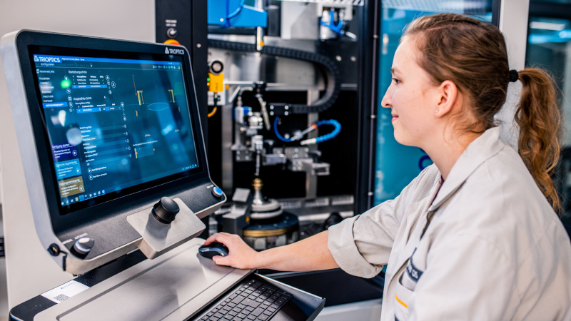
ATS – Alignment Turning Station
High-precision centering, alignment and machining of mounted lenses and lens groups
During alignment turning, the mount edge and the flange surfaces of mounted spherical, aspherical and cylindrical lenses are machined so that the axis of symmetry of the mount coincides with the optical axis of the lens. The ATS alignment turning machine combines the proven OptiCentric® centration measurement system with an ultra-precise turning machine. This makes it possible to adjust and control all relevant parameters while processing the mount, such as diameter of the mount or the distance of the lens from the contact surfaces of the mount. The high-precision measurement of decentering and the extremely accurate processing of the mount prevent cumbersome, iterative adjustment steps in the overall optical system. The intuitive operation results in operator-independent results during measurement and processing.

Versatile
All ATS alignment turning stations are suitable for a variety of samples and applications. Setup and adjustment of a new sample is done in a short time.

High manufacturing accuracy

High profitability
Streamlined processes, especially during subsequent lens assembly, increase production productivity.
Product Overview
ATS 100
The compact alignment turning station

ATS 100 is optimized for the processing of lens systems with a diameter of up to 100 mm and a weight of up to 3 kg.
ATS 200
The high-precision alignment turning station

ATS 200 is designed for processing small and medium-sized lenses in medium batch production.
ATS 300 UP
Flexibility in the lens diameter

Mounted lenses up to a diameter of 300 mm are machined with high precision by the ATS 300 UP.
ATS-C
CNC alignment turning for short cycle times

Built in a horizontal setup, ATS-C offers full CNC capabilities that allow for a swift integration of the machine to existing production processes.
Coffee Break
No time for long explanation videos?
Get the essentials on a wide range of technology topics during a coffee break.

Applications
Mounted lenses
With their universal design and versatile metrology options, the alignment turning stations ATS can process all mounted lenses and lens assemblies, including those with infrared and aspherical lenses or with mounted cells that cannot be glued. The choice always falls on the ATS when it comes to increasing efficiency. Here the system has not only excelled in mass production but also in the manufacture of customized lenses.
Laser diodes
Just like the alignment of passive elements such as mounted lenses, the ATS also allows the alignment of laser diodes. Here, too, alignment turning eliminates the need for active alignment of the laser during assembly. For these active samples, the generated laser beam serves as the centration axis. While the correction of the inclination is already possible in the sytem’s standard configuration, a second optical measuring arm must be installed for the additional correction of the displacement. The processing is carried out in the same way as for the passive elements.
Success Story
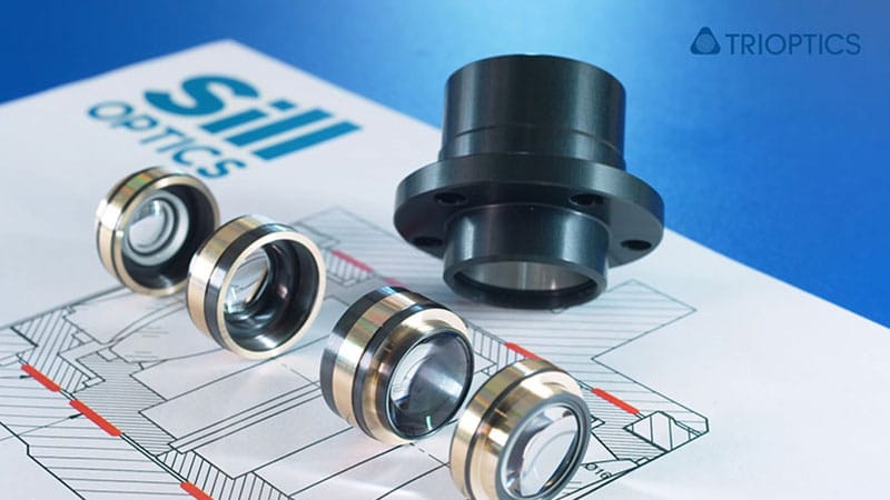
ATS increases the precision of lenses to a maximum at Sill
Sill Optics successfully implemented the TRIOPTICS Alignment Turning Station into their production process. Martin Kolb, Project Manager Laser Optics, explains the benefit: “When attempting to accurately align the mechanical and optical axes, conventional methods can result in deviations of a few angular minutes. These tilt errors would cause unacceptable inaccuracies in our high-precision multiple lens systems. Thanks to TRIOPTICS’ ATS, we can reduce the tolerances of residual tilt errors to a few arc seconds. Adjustment turning increases the precision of our lenses to a maximum. We therefore use the ATS regularly for our high-precision lenses.”
A quality leap in precision manufacturing at WILD
WILD recently added a new alignment turning station – ATS 200 UP – to its machine park. The machine is a pivotal element for utmost precision and efficiency in the manufacturing of complex optics.
”In future, alignment turning in the quality we can now offer will open the door to new designs with very small air gaps.“
Stefan Werkl, Head of the Optical Technology Division at WILD
ATS increases the precision of lenses to a maximum at Sill
A quality leap in precision manufacturing at WILD
Software
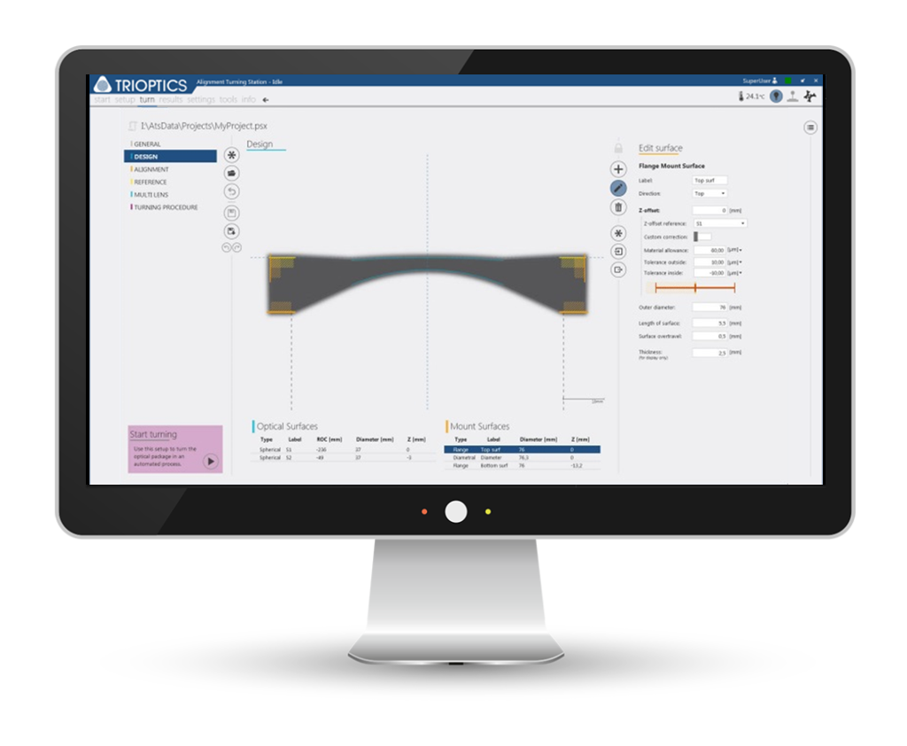
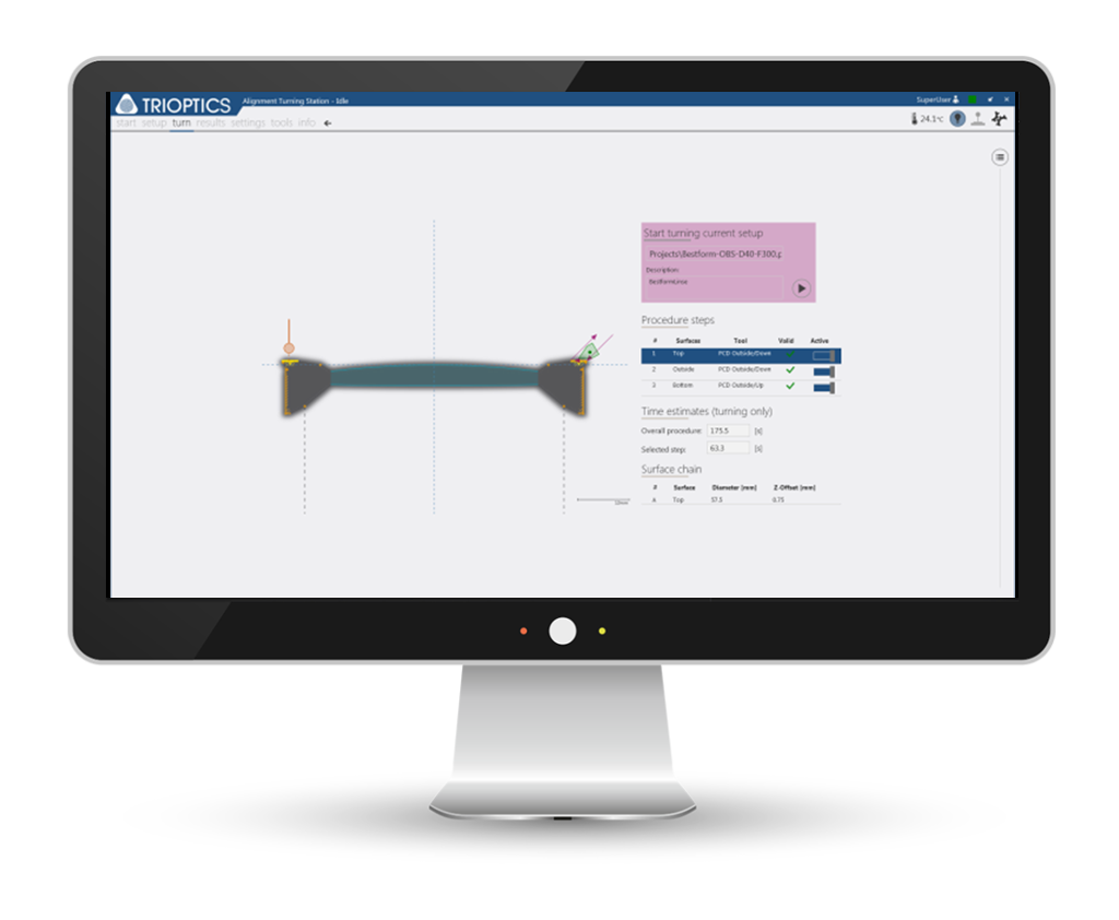
ATS Control
One software for all measurement and production processes
The ATS Control combines operation of the machine functions with the routines for measurement of centering error and alignment. The user is guided step by step, both in setting up sample geometry and carrying out the processing procedure. The software continually monitors the results of the production process.
Technical Data
| Parameter | ATS 100 | ATS 200 | ATS 200 UP | ATS 300 UP |
|---|---|---|---|---|
| Machine type | Mineral casting base | Granite frame | Granite frame | Granite frame |
| Spindle | Aerostatic | Aerostatic | Hydrostatic | Hydrostatic |
| Workpiece diameter | Up to 100 mm | Up to 200 mm | Up to 200 mm | Up to 300 mm |
| Max. workpiece weight | 3 kg | 5 kg | 5 kg | 15 kg |
| Workpiece material | brass, aluminium, NiP-Steel | brass, aluminium, NiP-Steel | brass, aluminium, NiP-Steel, invar, titan, steel | brass, aluminium, NiP-Steel, invar, titan, steel |
| Production accuracy | Up to < 2.5 µm | Up tp < 1.0 µm | Up to < 0.5 µm | Up to < 0.5 µm |
| Dimensions (h x w x d) | ca. 2.0 m x 1.0 m x 1.0 m | ca. 2.20 m 1.55 m x 1.10 m | ca. 2.20 m 1.55 m x 1.10 m + 1.65 m x 0.87 m x 0.65 m | ca. 2.20 m 1.85 m x 1.10 m + 1.65 m x 0.87 m x 0.65 m |
| Weight | approx. 1,400 kg | approx. 2,500 kg | approx. 3,000 kg | |
| Type | Stand alone | Stand alone | Stand alone | Stand alone |
| Parameter | ATS-C |
|---|---|
| Traversing speed UP axes | > 15 m/min |
| Spindle speed | 2500 min-1 |
| Process speed for alignment turning | ≥1200 min-1 |
| Workpiece diameter | Max. 200 mm |
| Workpiece length | Max. 150 mm |
| Workpiece weight | Max. 2.5 kg |
| Manufacturing accuracy alignment turning | Roundness ≤ 1 μm Flatness ≤ 1 μm |
| Programming resolution | 1 nm |
Upgrades & Accessories

- Aerostatic spindle
- Hydrostatic spindle
- Tactile sensor

- Optical sensor
- Temperature sensor
- Workpiece temperature sensor
- Sensor for aspheres

- Second autocollimator
- Quadruple tool changer

- Head lens changer

- Minimum lubrication
- Chip extraction
- 2D code reader

- Increases in efficiency by adding a robot to the ATS for automatic loading and unloading.

- Cutting of threads and grooves
- More information
Knowledge Base
Measurement and alignment turning of optical assemblies
Alignment turning is the only method by which relevant parameters of a mounted lens can be aligned, in particular the gap between two apex points and the contact surface. In addition, a large number of different cell sizes can be processed. And finally, high precision turning machines achieve excellent production accuracies of up to 0.5 µm.
More knowledge for experts
This article inspired you? Are you looking for further knowledge transfer?
Then you might also be interested in the following topics …
Alignment turning with alignment chuck
The alignment turning method using an alignment chuck is described in the figures below (Fig. 3). Here, first the lens cell is fixed in an adjustable alignment chuck with the lens in place. Then the position of the optical axis of the lens to the spindle axis is measured with the OptiCentric® system. Using this alignment chuck, the lens is then aligned so that its two centers of curvature are located as closely as possible to the axis of rotation of the spindle.
Then the spindle is rotated and the contact surfaces of the cell are machined with a sharp (diamond) turning tool, resulting in a precisely machined surface of the cell, aligned parallel to the spindle axis. In addition to the outer surface of the cell, it is also possible to machine the front and rear contact surface during the turning process. To do this the turning tool is moved perpendicular to the spindle axis instead of along the optical axis.
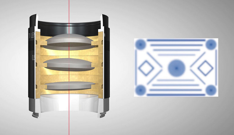
Fig.1: The optical axes do not coincide with the axis of the barrel; lens distances are not correct
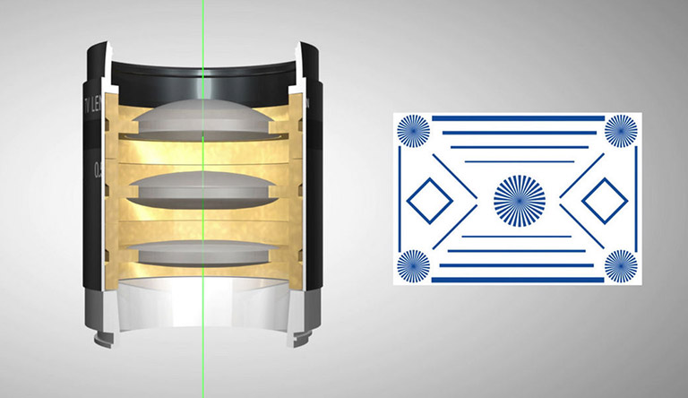
Fig.2: The optical axes and the axes of the barrel coincide, lens distances are correct
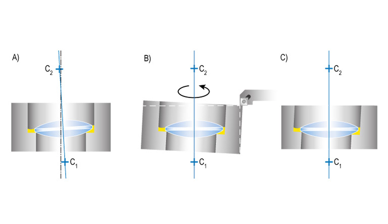
Fig. 3: The alignment turning process A) optical axis of the lens is determined, B) & C) cell is aligned to the optical axis of the lens, the edge of the cell is machined so that it is parallel to the optical axis
CNC alignment turning
Alignment turning on the ATS-C is implemented without an alignment chuck. The mounted lens is held on the horizontally mounted spindle and the optical axis is measured with OptiCentric® measuring technology. To adjust the mounting surfaces to the optical axis, the turning tool moves in x- and z-direction.

Variable preconditions and options
The lens is already fixed in the cell during the alignment turning process. This means that low-stress adhesives with very long curing times can be used for highly precise optics. Similarly, the lenses can be crimped or held by screw rings when the available adhesives are not suitable for the intended application. In order to achieve high accuracy TRIOPTICS has integrated additional measurement technology into its alignment turning stations, alongside the high-resolution autocollimators. These include tactile and optical test systems that ensure a highly accurate measurement of the relevant mechanical parameters. This means the highest precision is achieved by a gradual machining process, in which the cell accuracy is checked after each machining step. The cells used in alignment turning do not need to meet exceptionally tight tolerances before machining. The cell offset only needs to be large enough to meet the required tolerance after machining.
The distance from the lens vertex to the upper contact surface can be manufactured with an accuracy of up to ±0.5 µm. Similarly, the diameter can be manufactured with an absolute accuracy of ±2 µm. The remaining centration error can be reduced to less than 0.5 µm by using a suitable alignment chuck. Moreover, a low coherent interferometer can be used to measure the center thickness on the machine, so that the contact surfaces can be manufactured with high precision with respect to each lens vertex. Multiple mounted lenses manufactured by alignment turning are then assembled to an objective lens. The method of machining in the micron range ensures that all lenses are aligned to each other. This allows mounted lenses to be assembled in a tube without further adjustment steps